Like last time I posted here, there’s been much progress. In fact, the controller is already working, even though everything isn’t finished yet. So, let’s start where we finished last time. Faders!
Placing faders
As I’ve already stated, I had some issues with placing the faders. Main source of issues was that I didn’t have any 2mm screws to screw them to the plate. As I’ve found out, those tiny screws are incredibly hard to find, at least in my area, so I had to figure out something else.
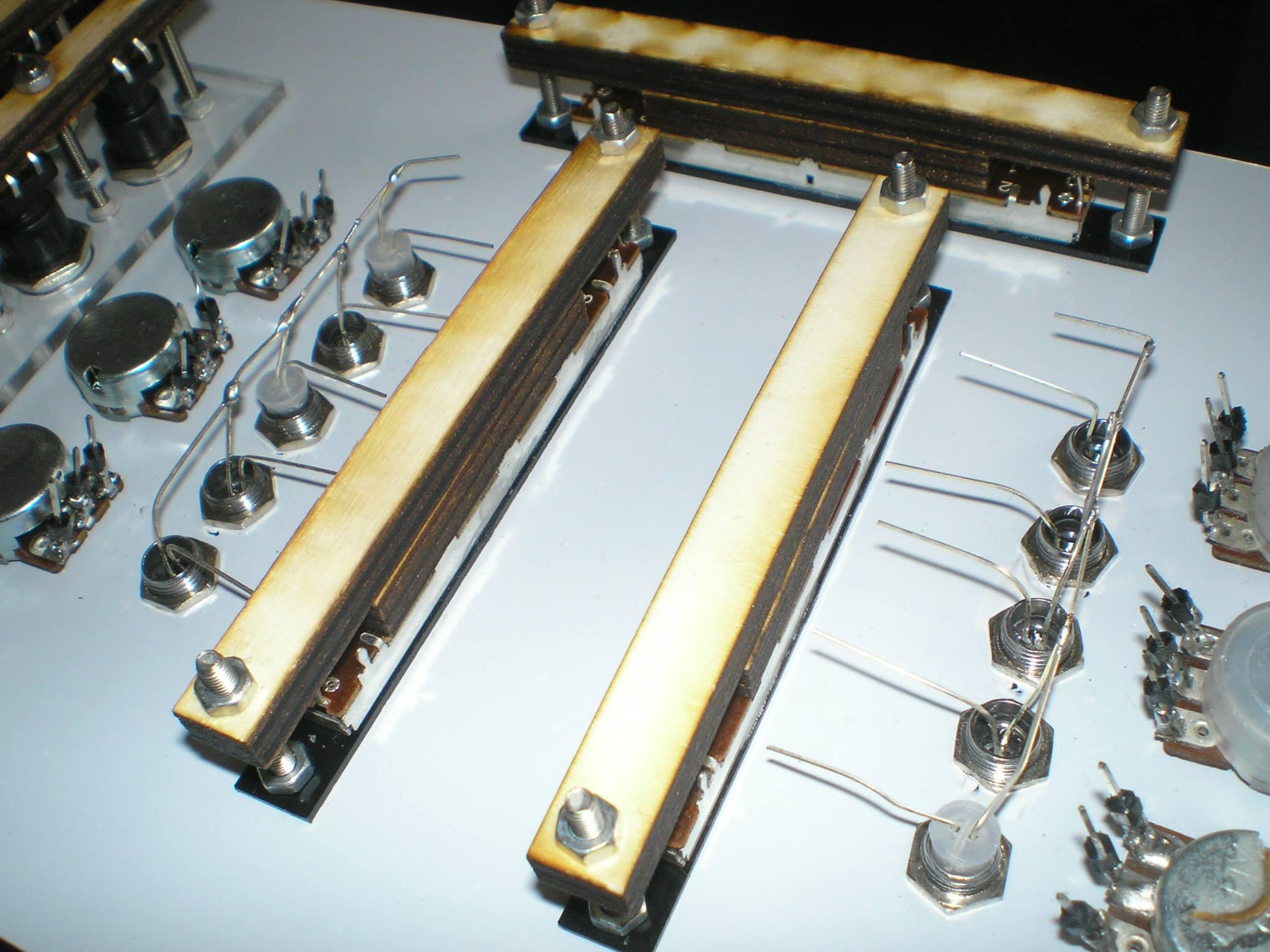
Above each fader, there is really thin piece of plastic board super-glued to its surface. Couple of mm away there is standard 3mm hole. To make it more stable (otherwise that plastic would’ve fallen off) there are wooden holders screwed really tight so that there’s no way anything can happen with faders. Wooden pieces on left/right fader are shown here only for reference, as I designed PCB to fit between those two faders, but more on that later. Pretty dirty hack, as it involves extra stuff like wooden pieces, plastic and superglue. And, as the only real constant in universe says “thou shalt not use superglue without supergluing thyself”, I managed to spill some glue on my sweat suit. :( So yeah, building MIDI controllers is dangerous. You have been warned.
Worth of mention is that all of this would never happen if I had those damn small screws! I eventually ordered bag of them from eBay, when I finished all this, since eBay shipping times are getting horrible lately, and I wanted to get this done as soon as possible.
PCB
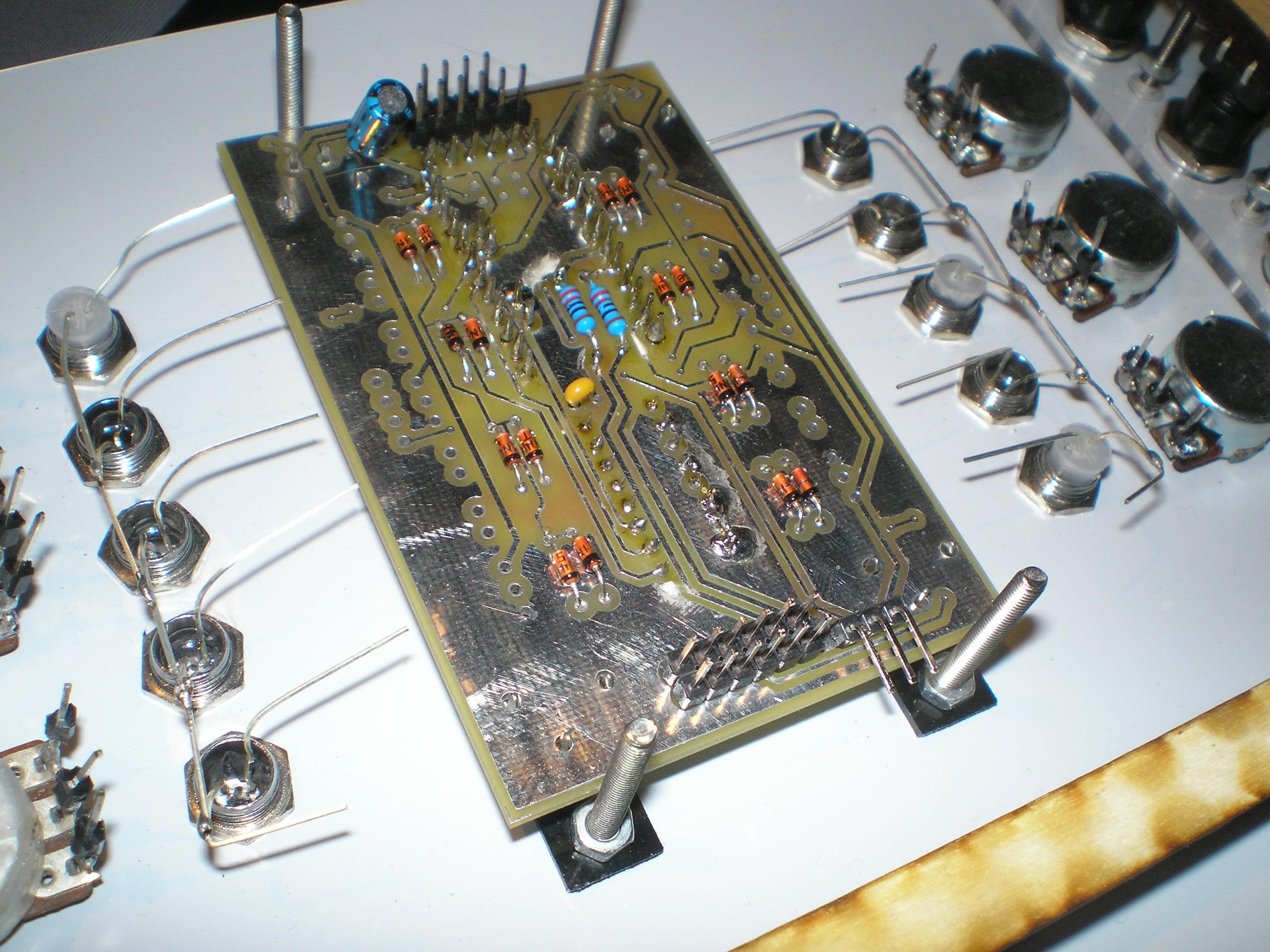
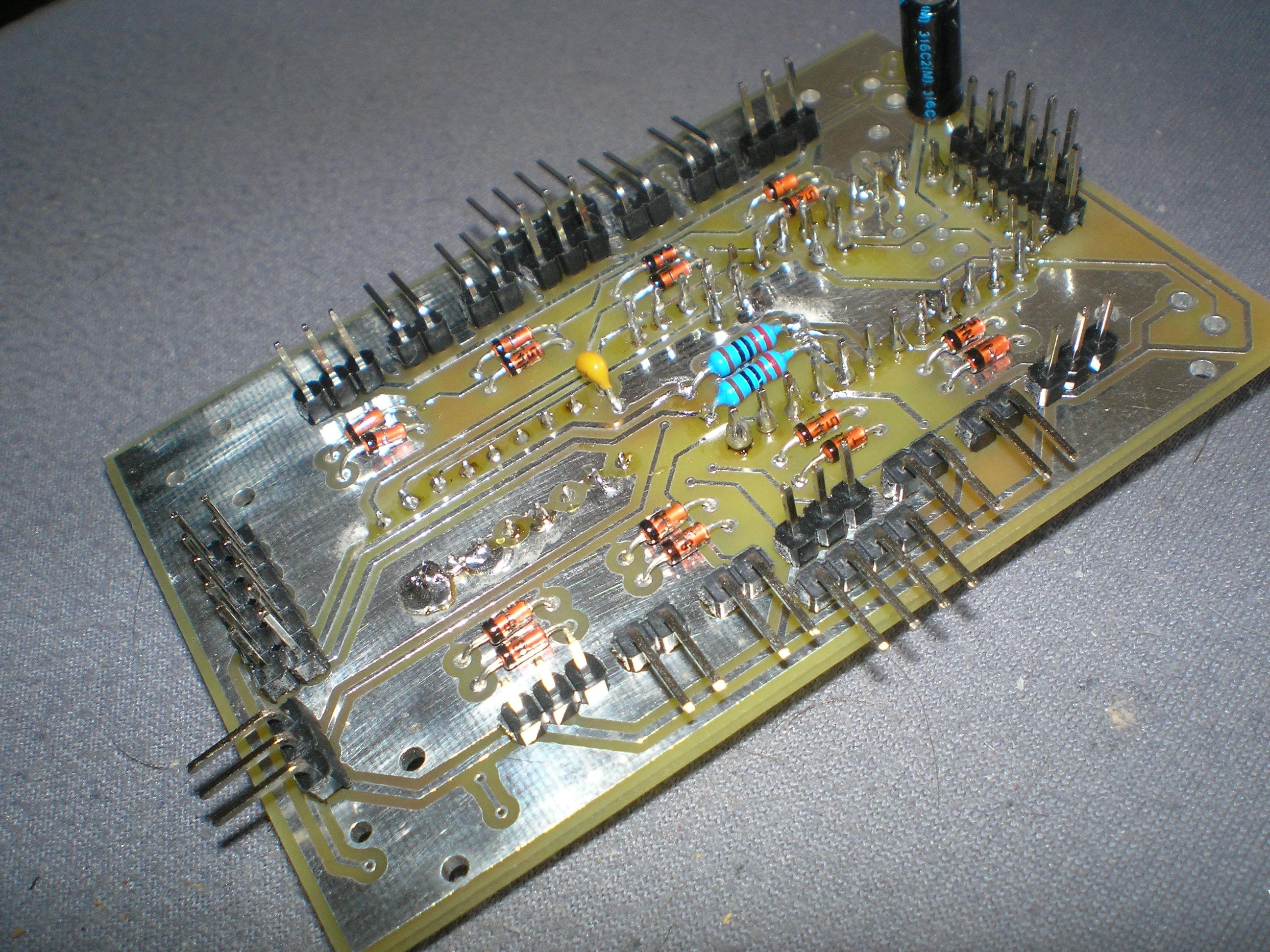
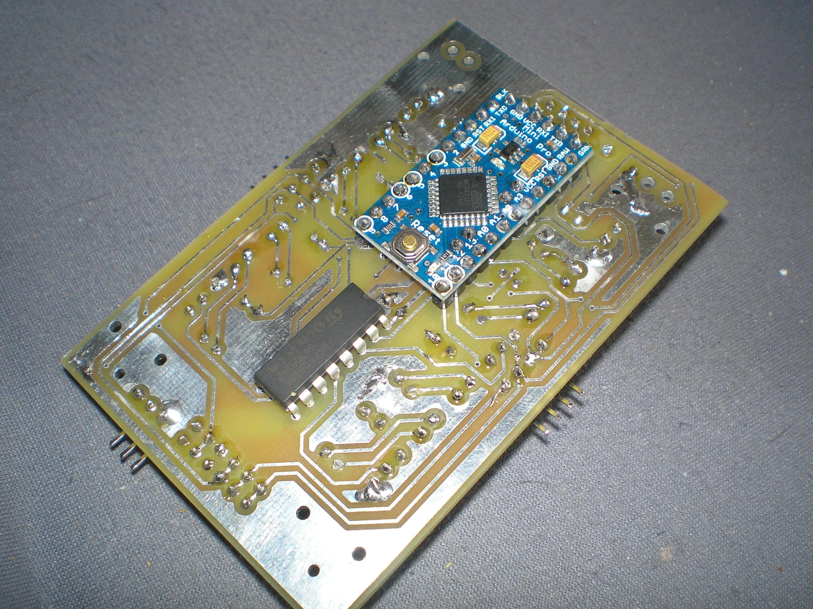
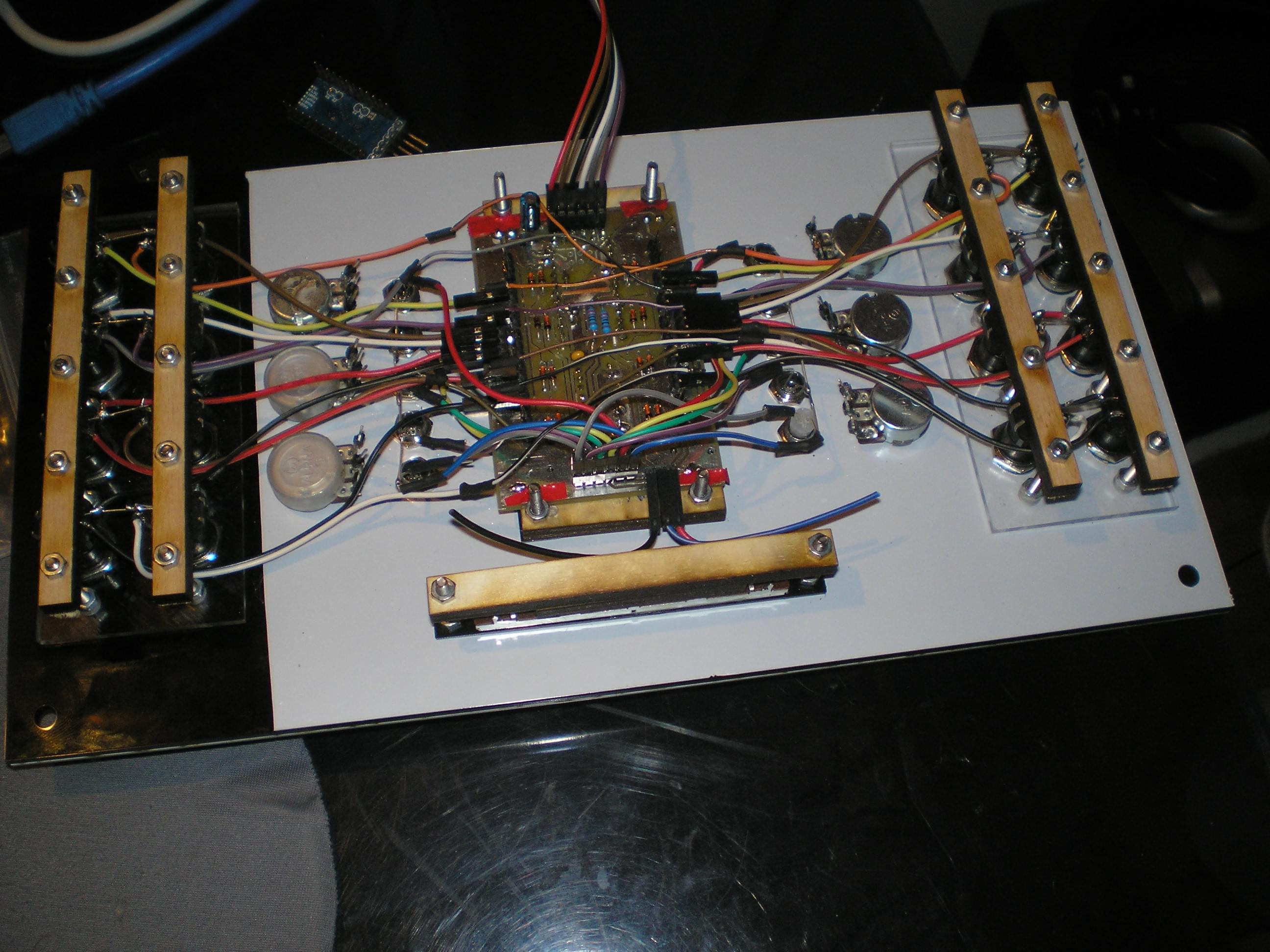
I’ve done PCB schematic in EAGLE CAD, my so-far favourite PCB design application. The board houses Arduino Pro Mini, two resistors for LED rows in matrix, 16 diodes for buttons in matrix to enable multi-press, 4051 multiplexer for potentiometers and couple of capacitors to make everything run more smoothly. There’s also lot of pin headers for wiring LEDs, buttons and fader. Pretty simple schematic, but prone to errors like everything. After all, what is a project without issues? There were three issues in total with PCB, but luckily, all are solved.
The board dimensions
PCB has been designed to fit between left and right fader, to make wiring more efficient and easier. Unfortunately, I completely forgot that I have to pay attention to board height, as those 3 mm screws actually set the height limit. To my good fortune, lower dimensions were okay and upper needed a bit of trimming with sandpaper. Luckily, I’ve checked the design in EAGLE with upper few mm cut off, to see if that would mess with ground planes. It didn’t! One issue solved.
Button matrix and diodes wiring
This issue popped out after I’ve finished wiring all the buttons. So, I connected the controller in PC to check if everything is OK with buttons. Yes, they all worked, but eight left buttons registered as only four buttons, and same thing happened on the right side. Basically, pressing buttons next to each other showed up as same button. A bit of inspective work later, I found out I made really stupid mistake of connecting two buttons under same row and column on PCB design. Ugh!
The fix consisted of soldering four buttons on the left to right side of PCB and vice versa. Not too much of a problem, but after that I had 8 wires in total soldered directly to PCB, which really broke my modular design, as I wanted each component to be un-pluggable.
Ground issues
This is probably the last time I’m ever going to build something with PCB without protective layers. Only reason I did it this time is because I ordered PCB from local shop from which I can get PCB done in a few days, but the prices are absurdly high compared to ITead studio, for example (I found out about that site after I already sent PCB to production, of course). Ordering 10 of those boards from ITead with protective layers, silks etc. would’ve costed me LESS than single board I used here, without any of those layers, just plain double-layered board. Ugh. Lesson learned. Anyways, after I connected pretty-much everything, the LEDs started to behave weirdly, as well as two buttons (their presses showed up like pressing couple of buttons instead of only one). Again, some investigation revelead that one of my columns in matrix-setup was connected to ground. The reason it did is because after I soldered PCB to faders, one tiny bit of PCB surface touched a piece of metal part on fader, short-circuiting that column line to ground. With protective layers this would’ve never happened. What I had to do was to un-solder faders, disconnect every wire from PCB and also to un-solder those 8 wires from issue #2 (somehow I knew sooner or later I would have to do that, things just DON’T work at first, second or third try). After that I’ve put some isolation tape across whole bottom of both faders, and also on PCB to places where I connect faders, just to be sure. Messy bussiness again, but I fixed it.
After solving all the issues with PCB, everything worked. Below the board there are two wooden pieces, put there so that I can screw the four screws to secure both the board and faders, and also to avoid bending of PCB.
The box
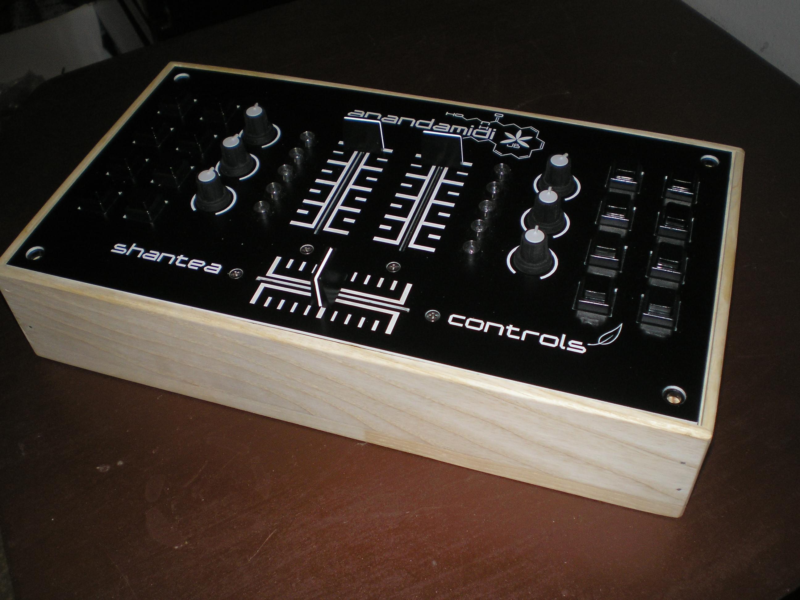
After I finally solved all the issues with electronics, I was still left with couple of other things. The first was the case. It’s a fairly simple wooden case, and the guy who did it has done pretty good job. Things can always be better, but sometimes they don’t have to be.
Remaining stuff:
- Painting the case (black!)
- Interfacing Arduino with separate USB MIDI chip on separate PCB
More on that next time!