In this post, I’ll be talking about build process of my latest and greatest MIDI controller; Tannin 2. It took me almost 5 months to actually finish it since there were so many architectural changes in it that I basically started from scratch.
The design
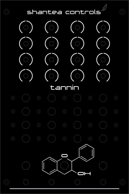
Tannin 2 design is, naturally, very similar to the original Tannin controller (incidentally, I never actually wrote a post about that one since it was finished some months ago before I started this blog). Since Tannin 1 is first Shantea Controls controller ever built, it has a special meaning for me - not so much as a physical product since it’s disassembled (I used some of its parts for Tannin 2) - but more as an idea. I had to make sure that Tannin 2 would be a worthy successor. For the reference, here’s the rendering of original Tannin controller:
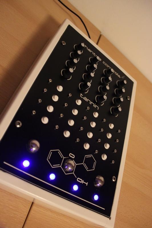
Assembled controller:
And one from the back:
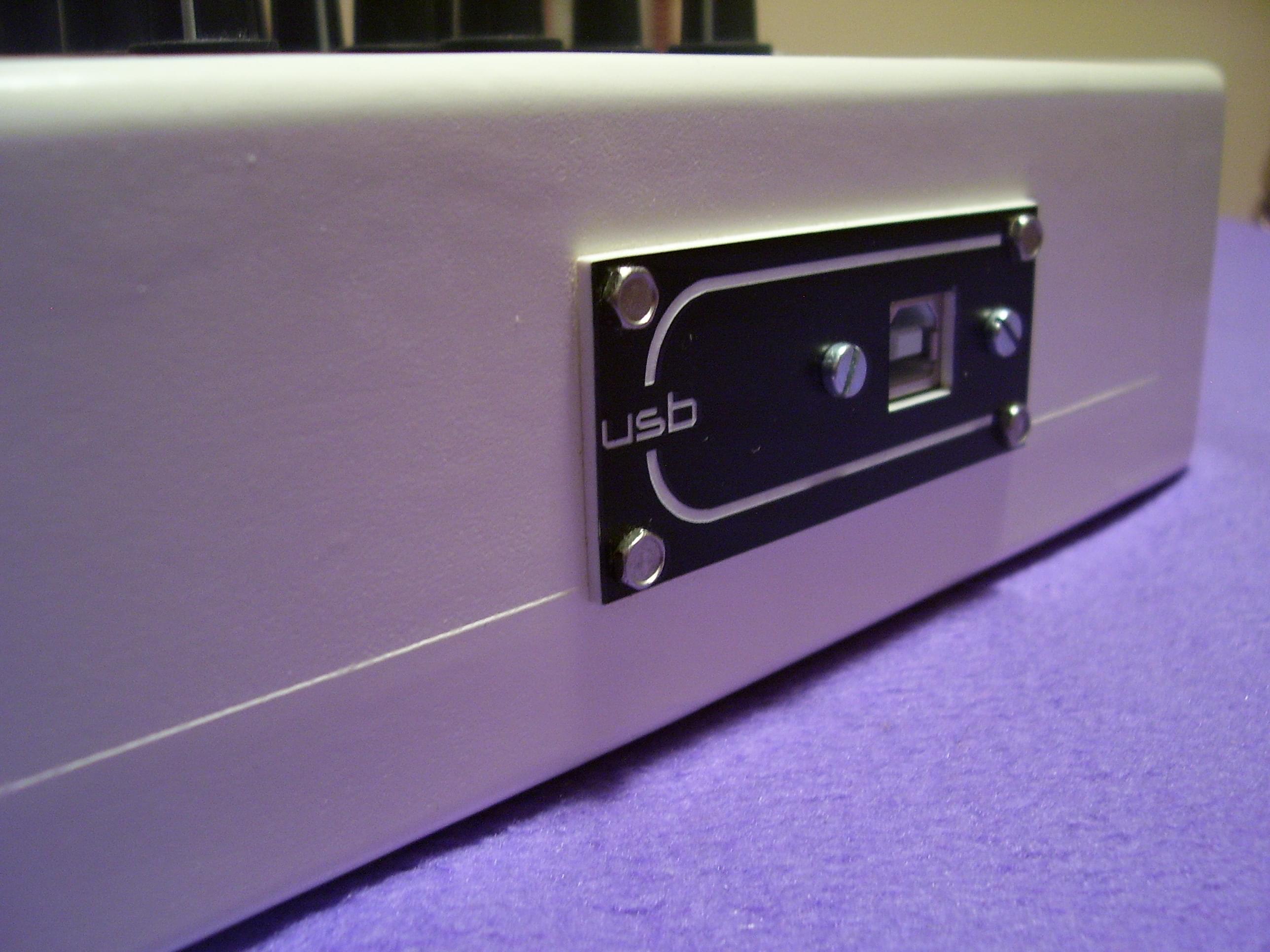
I can assure you it looks much better on the pictures than it really looked.
It had 16 potentiometers and 16 buttons in 4x4 grid, 3 additional metal buttons and 4 LEDs at the bottom. Very simple and very efficient layout. Over the time, I got used to it so much that I mapped virtually every function I need in my DJ software (Traktor Pro) using nothing but this controller. Still, it was my first controller, and naturally it had some flaws. First and most obvious one, there were too many screws. Second, that box was huge, too heavy and after few months it started to crack all over the place. It was also such a pain in the ass to carry around. On the hardware side of things, it featured Arduino Nano and circuitry that later became the basis for OpenDeck board. If you’re wondering what’s that chemical - it’s Flavan-3-ol.
So, now that we have Tannin 1 as a reference, let’s move on to Tannin 2.
Tannin 2 was imagined to be an improvement in every area - not just the flawed ones. When I thought about the design, I was trying to figure out what was missing in original controller. First of all, I wanted better buttons than those tactile ones and more LEDs. I also wanted either faders or encoders. Eventually I discarded the faders idea since it was impossible to fit them in same dimensions (I wanted to keep plate dimensions exactly the same - 200x300mm). So, after some consideration, this is what I came up with:
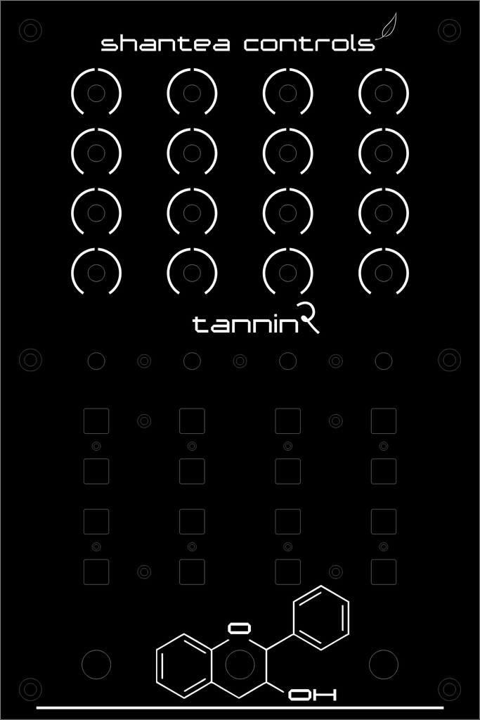
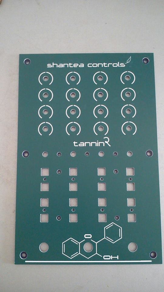
As you can see, design is really similar to original Tannin, but with few tweaks. Below 16 potentiometers, I wanted to have 4 encoders, and under them 16 silicone buttons with white LED inside each of them. 4 LEDs at the bottom got removed since a) I didn’t have much room left, and b) who needs 4 LEDs at the bottom when you have one in each button above? Potentiometers and metal buttons remained the same. I also added number 2 to Tannin name, even though it actually looks like letter ‘R’. Tannin Remixed? Acceptable as well. Notice that there are only few screws in this one. All in all, I was happy enough with that layout to proceed to actual build process.
Plate
As with the Ceylon controller, I wanted to experiment a bit with plate color. This time, I picked green one, and it really looks great - same as any gravoply plate.
The case
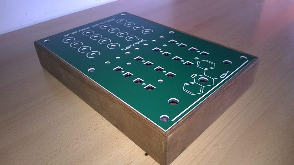
Until I built this controller, cases were always source of biggest frustration, since - let’s face it - they looked like crap, and thus ruining the overall feel of entire controller. Well, I didn’t want to go through same story again, so for a couple of weeks I was searching for someone who would do the job right. Whether or not I was successful, judge for yourself:
And back.
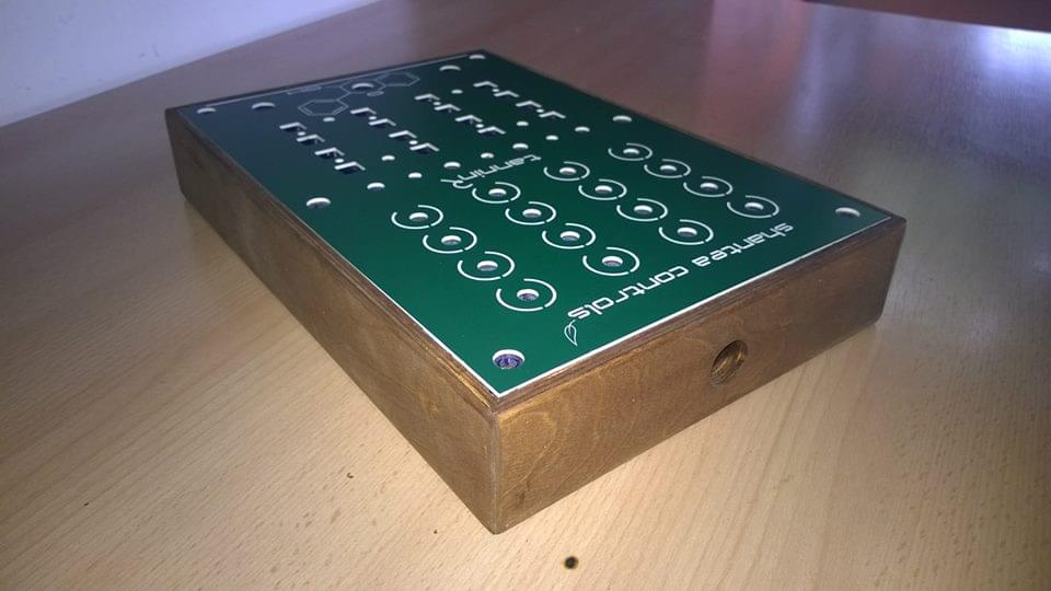
Finally, I have gorgeous case! That green plate really blended well with the tone of the wood. Also, its weight is just about right, not too light (it’s wood after all), and actually not heavy at all. Perfect!
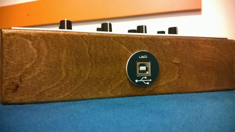
One more thing - I redesigned USB cable plate:
Electronics
For second revision of Tannin controller, I decided to use PCBs crafted specifically for Tannin 2, instead of using OpenDeck reference board. This proved to be a very challenging task, as I literally had to do everything from scratch. The main premise behind designing electronics for this one was that I was going to use ATmega32u4 as microcontroller. In the past, I used either Arduino Nano or Arduino Pro Mini. Both of those boards are fine on their own, however, the biggest drawback to using them is that they have no native USB capabilities. In practice, this meant that I had to use serial-to-usb adapter to program them and couple more layers of software to make them talk MIDI. In my commercial designs I also used those boards, but in addition to main board I used USB MIDI board which translated serial signals from Arduino to USB MIDI. Works just fine, but that USB MIDI board doesn’t support MIDI System Exclusive (primary method of configuring the controller) and it represents additional hardware. So, using ATmega32u4 solves both of those problems since it has USB built right into the chip. In case you didn’t know, Arduino Leonardo, Arduino Pro Micro and Teensy 2.0 use that exact microcontroller, however, this time I needed my own custom board. I needed it to be as small as possible - so Leonardo was discarded right away, I needed pretty much every available pin - discarded Pro Micro at this point as well and I also needed ability to use a custom bootloader for uploading new firmware to board. Now, you absolutely can put a new bootloader on a Teensy board - but you can’t upload the new code on it using Teensy loader then since that bootloader is proprietary, an aspect of Teensy I’m not particularly fond with. So, when you put new bootloader on Teensy, what’s the point of buying Teensy in the first place? Also, it was cheaper to buy pure ATmega32u4 chip with few external components than buying Teensy. I’ve been delaying this design with each controller since I figured that soldering SMD is going to be much harder than soldering standard DIP packages. I was right, but just because it’s harder doesn’t mean it’s impossible. You just need steady hand and some patience. The final result was this:
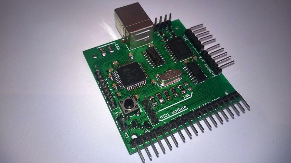
Only 5x5cm! Obviously, main component is ATmega32u4, the mighty brain which does all of the processing. Next, it features my standard hardware for LED/button matrix, 74HC238 decoder and ULN2803 current sink. For reading button rows, this time I added 74HC165 shift register. I had few 4021 registers lying around, but 165 register can work a bit faster, so that’s why I’ve chosen it. I also added reset button, ICSP header so that I could program it with external programmer (USBasp) and also MIDI header, which is nothing more than +5V, GND and RX/TX serial pins from microcontroller. Having them on header allowed me to test hardware MIDI on this board as well, and it works! This means I can expand this board with real DIN MIDI in/out connectors. Not that I have any use for it at the moment, but since this board will serve as a basis for OpenDeck v2 reference board, I wanted to see how it’s going to behave. Board also features pin headers on the edges to connect potentiometers, buttons, LEDs and encoders. One resistor is missing in this picture - at that point I was unsure what to do with HWBE (hardware boot enable) pin on ATmega, but more on that later.
Now, having the main board finished didn’t mean I was done with electronics. At all. First of all, those silicone buttons needed a PCB. Encoders also needed a PCB, and potentiometers as well. That’s lots of PCBs. I ended up designing a single 10x10cm board with panelized designs for each part. In total, I needed 4 separate PCBs for buttons, 2 boards for encoders and 2 boards for potentiometers. I also needed a small board for USB connector which would be housed in the box. Luckily, I managed to fit all of that in a single board, and the guy who cuts gravoply plates for me also did the cutting of PCBs.
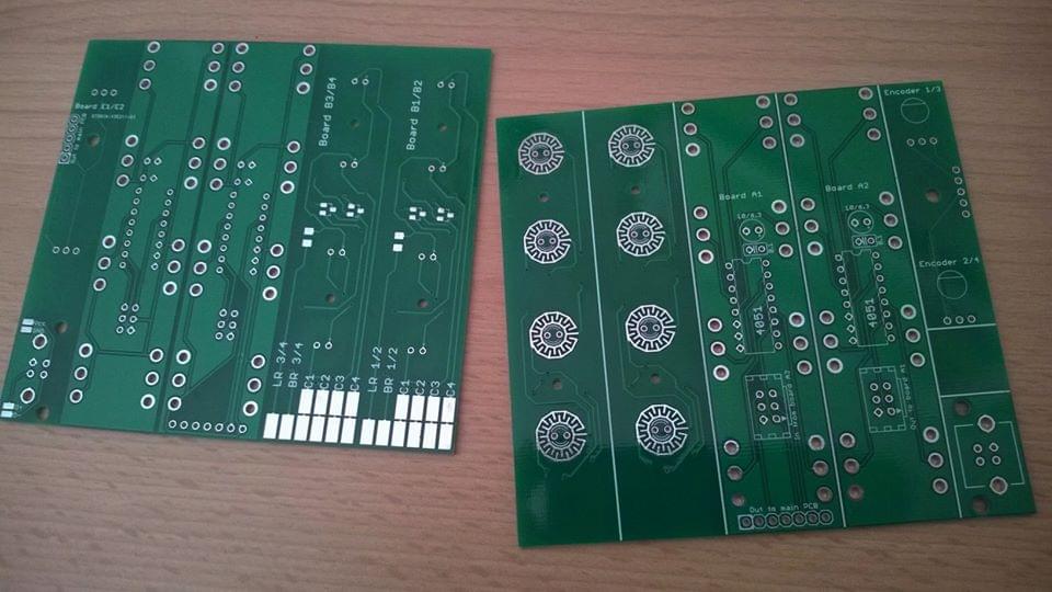
To make one controller, I actually needed two of those boards, however, you can’t order less than 10 pieces, so that wasn’t a problem.
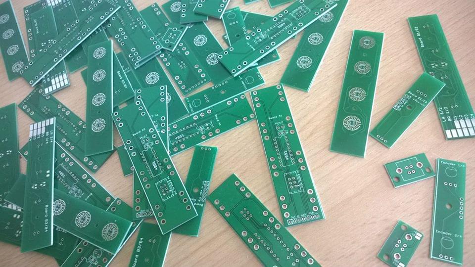
Free candy! I mean PCBs!
This is how Tannin 2 looked inside after first round of soldering:
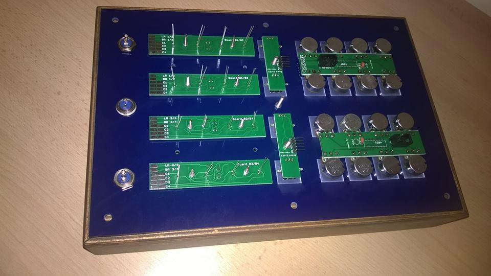
Analog boards feature one 4051 multiplexer each. One of them is “slave”, other is “master”. This only means that slave (right one) connects to master (left one) using 6-pin IDC cable. That allowed me to use only 7 wires from master analog board to main board. Encoder boards feature 5 pins each. Both boards also connect to main board. Four boards with LEDs and silicone buttons have shared columns, so each board connects to the next using four wires. Finally, those four wires are connected to main board. Boards also have one LED/button row wire each, so that’s two additional wires from each of the four boards to main board. Three metal buttons below also connect to main board on assigned pins.
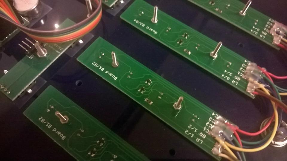
I used some hot glue to ensure the wires don’t move and break. Each board has one resistor for LEDs and 4 diodes for button matrix (there are actually 2 diodes per package so there are 2 packages per board). Diodes for three metal buttons are placed on main board.
Since encoders are nothing more than a two buttons, they are connected in separate button matrix. Reason for separation is that button/LED matrix switches columns every 1ms, and that’s too slow to read encoders properly. Setting the matrix to faster switching rate would result in LED flickering since I also needed PWM for LEDs.
Final look inside:
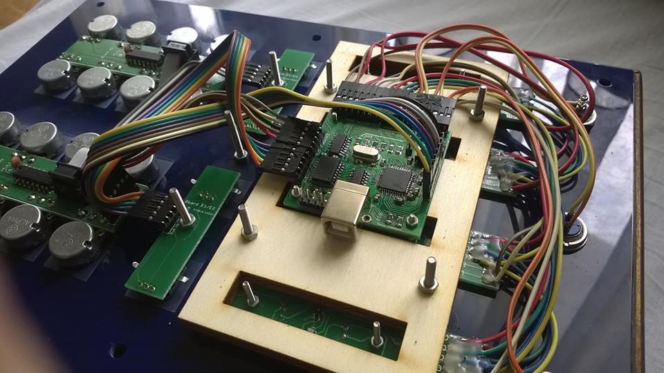
That wooden part makes sure the button PCBs don’t bend. Also, main board is designed so that it fits perfectly on four screws holding two PCBs together. Finally, I added some hot glue to secure all contacts:
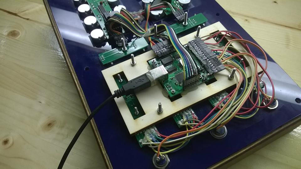
Entire schematic will be available on my GitHub at some later date.
Software
As I mentioned before, Teensy 2.0 board uses ATmega32u4, same microcontroller that I picked. Even though Teensy boards are compatible with Arduino, software is of much higher quality and they can also be programmed as USB MIDI devices, something Arduino boards aren’t officially capable of doing (at least in Arduino environment). Selecting Teensy 2.0 board in Arduino IDE and then trying to upload it to Arduino Pro Micro or Leonardo won’t work because Teensy uses Teensy Loader to load software on board, which in turn communicates with their HalfKay bootloader, which you can’t download. However, I needed that USB MIDI stack that Teensy boards provide. So, I simply connected my main board to USBasp programmer, selected Teensy 2.0 as a board, USB MIDI as device type and uploaded it to board. Note: if you want to upload code to Teensy/Arduino using external programmer, simply hold shift and then press upload. That worked flawlessly! Board immediately showed up as Teensy MIDI on my computer. Awesome! Now, the hard part was moving all of my existing OpenDeck code to Arduino-style format. In the process, I integrated most of Ownduino functions directly into OpenDeck library. I could talk about the software part for hours, but you can easily check the code yourself on my GitHub. This was all very nice, but every time I needed to change something in the code, I needed to connect external programmer to main board. In practice, this meant constant opening and closing of controller - quite tedious. I needed a bootloader and I found one. It’s called USB Mass Storage Bootloader and it’s really fantastic. After you reboot your board into bootloader mode, your PC shows a new device connected to your PC: removable drive! It shows two files: EEPROM.bin - which contains all parameteres stored into EEPROM (obviously) and FLASH.bin - the compiled code. To upload new code, simply delete FLASH.bin, copy new one, eject the drive (very important - ejecting it actually triggers the upload process), and then simply reconnect controller to USB.
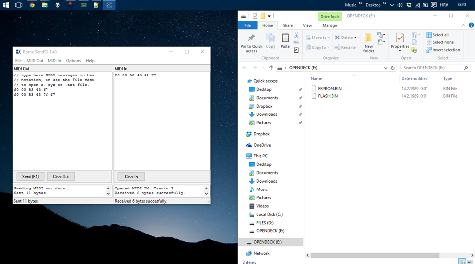
The trouble I had with bootloader was that the controller was constantly turning on in bootloader mode - it never showed as MIDI device. Later I found out I need to change certain fuses on microcontroller. USB AVR microcontrollers generally have two fuses responsible for deciding whether to run user program or bootloader: BOOTRST and HWBE. If you enable BOOTRST, microcontroller is going to run bootloader everytime it’s reset. HWBE, on the other hand, acts a bit differently. If you enable HWBE and disable BOOTRST, your device will reboot into bootloader only if HWBE is shorted to ground before you turn on microcontroller. This is why you need to hold reset key on certain devices before you can update firmware on them. I figured I don’t really need any of these fuses, so I disabled both of them. I want microcontroller to always run application program, and bootloader only on demand. To trigger the bootloader reset, I need to send specified MIDI System Exclusive message to controller. After that, controller reboots into bootloader mode, showing as a disk drive. Just what I want. Great! Another puzzle was how to generate that FLASH.BIN file? I only use Arduino IDE for testing out stuff and use Atmel Studio for any bigger project. After you compile project in Atmel Studio, it generates .hex, .elf and few other files inside your project directory. You can also define “external tools” in Atmel Studio. I defined one such tool to convert .elf to .bin. Basically, you need avr-objcopy tool with these parameters:
-O binary -R .eeprom -R .fuse -R .lock -R .signature <compiled\_project>.elf FLASH.bin
I only need to figure out how to do that automatically after compilation so that I don’t have to manually invoke the command.
Conclusion
This is how controller looks right now - fully assembled:
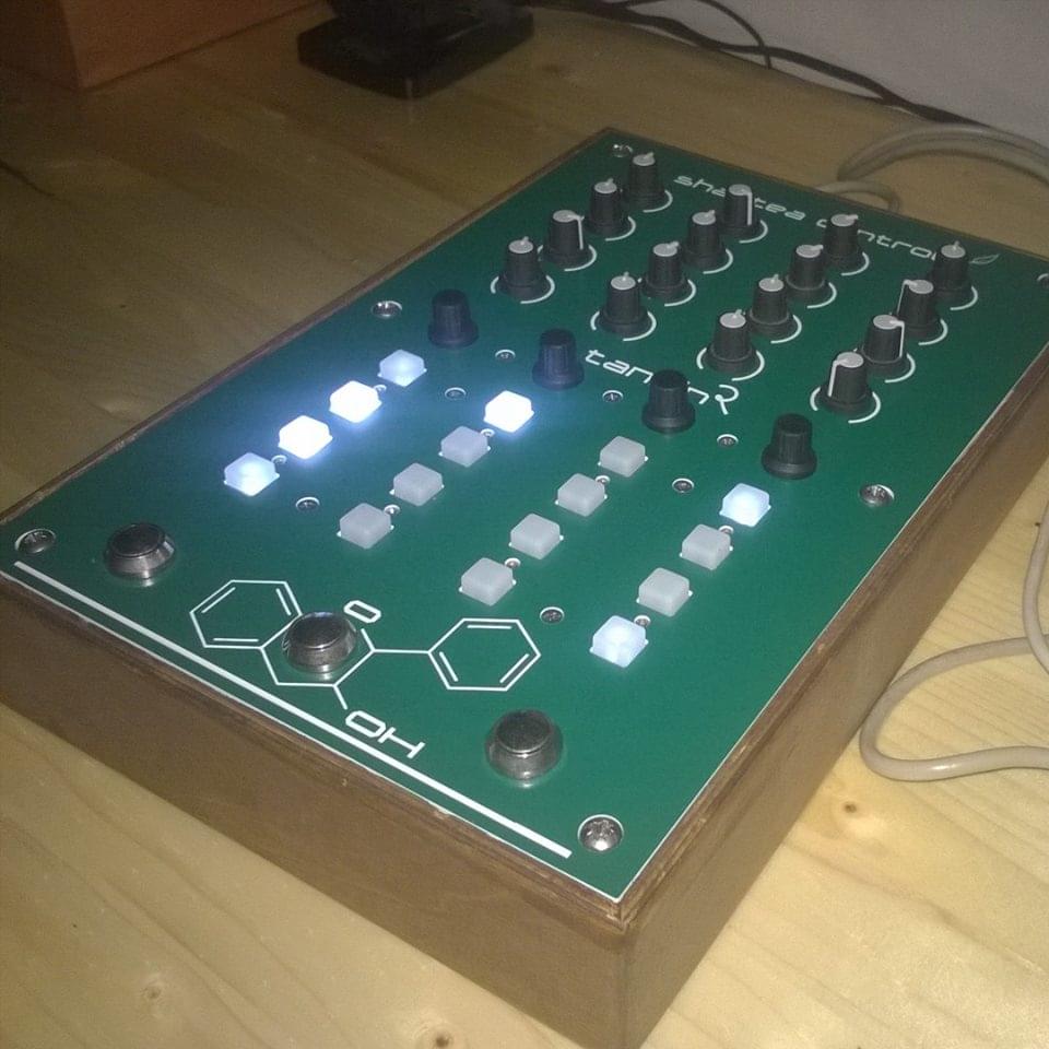
So, here’s a quick video showing Tannin 2 in action. Notice how LEDs fade now - I finally added PWM support with selectable fading speed using System Exclusive.


