This is a long overdue post about Ceylon, another Shantea Controls controller, only this time, one that I’ve built for myself. Of course, it’s based on OpenDeck platform.
Ceylon was actually built about three months ago. Reason why I haven’t written about it is a combination of things really. First, it was in a beta period for more than a month, and after that I just didn’t have much time to write posts, as I was really busy (and still am) with other projects that I’ll hopefully write about soon.
Name and design
Let’s start with a name. After Anandamidi and Sensimidia, it was time to bring back tea in Shantea Controls again. So, Ceylon is actually well-known high-quality tea originating from Sri Lanka, former British colony known as Ceylon (hence the name). There are couple of variations of it, black one being my favorite (with some spices of course, that is, loads of ginger).
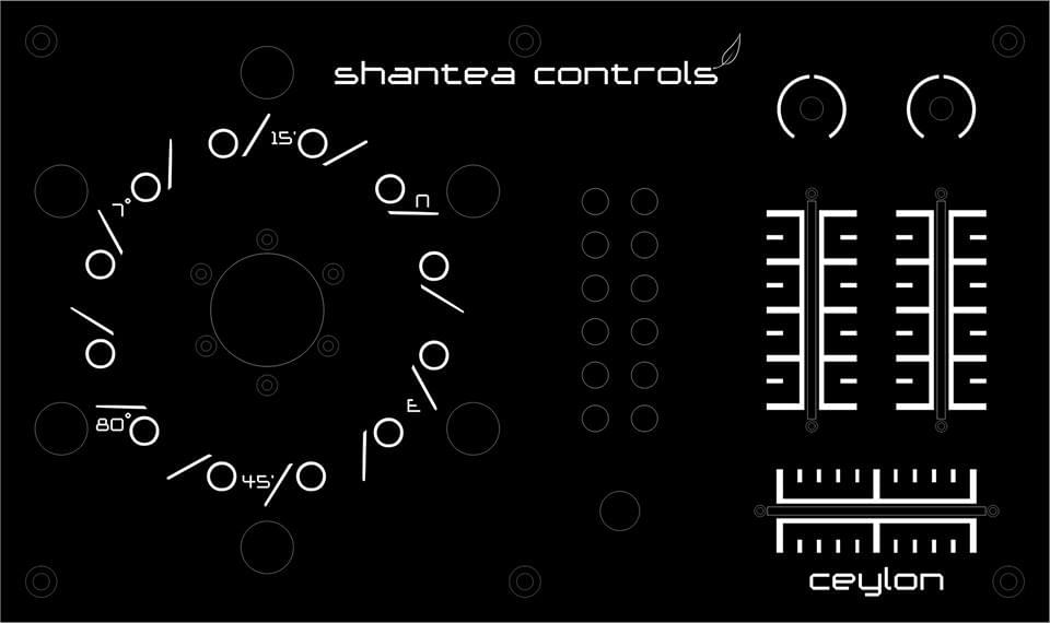
Picture above is a rendered drawing of Ceylon design. Numbers around the circle are coordinates of Kandy District, heartland of tea production in Sri Lanka. So there you have it, a Ceylon story!
Layout
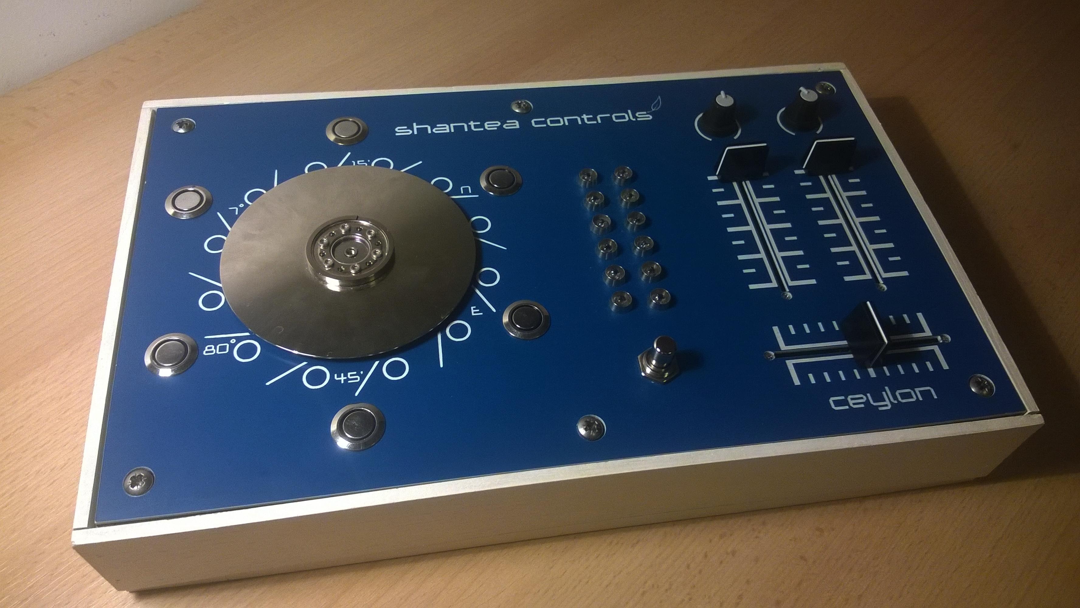
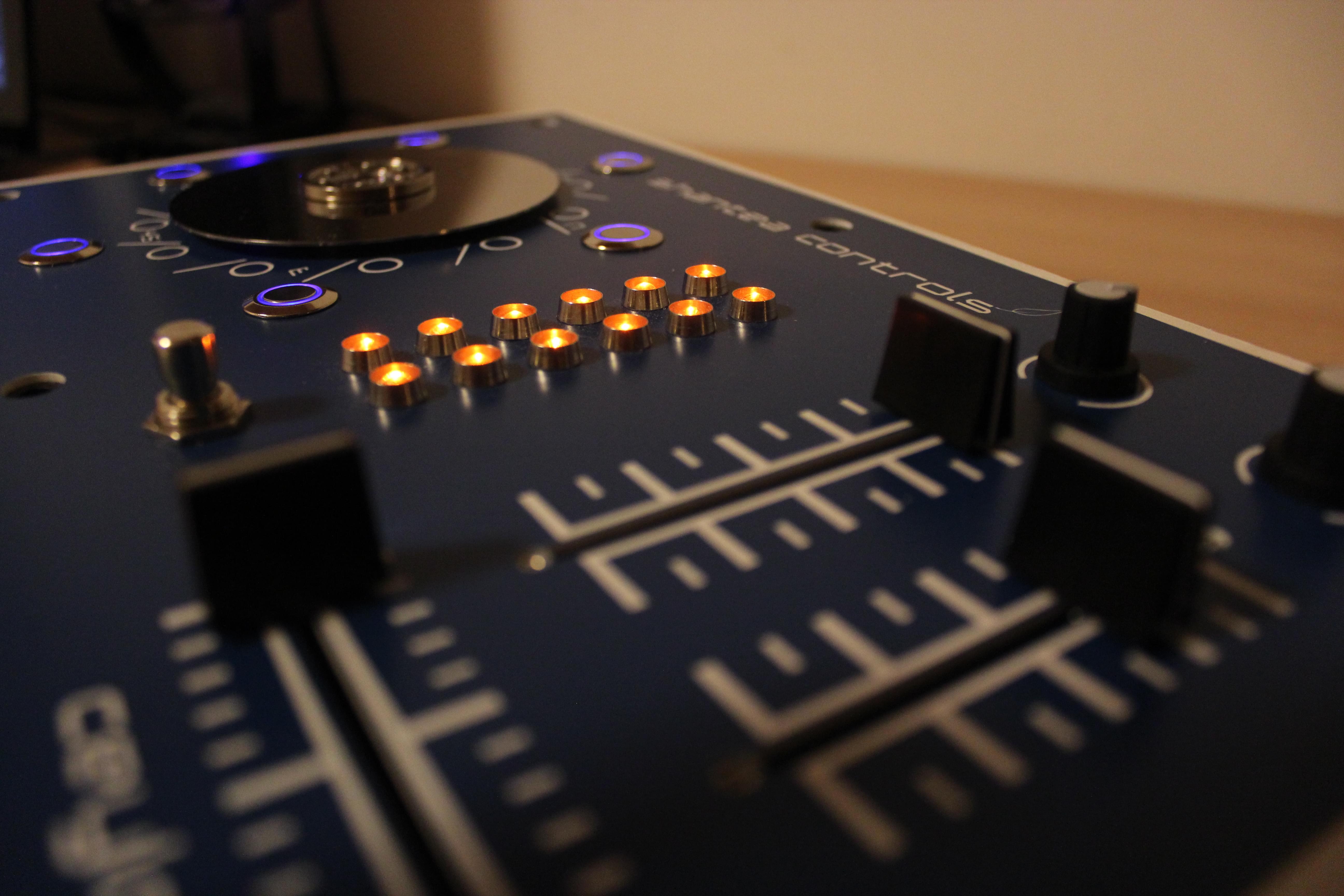
Since Tannin was my only controller so far, I’ve mapped nearly every function I need, so when I started designing my second controller, I wanted something really simple that would complement Tannin well. There was no need for a complicated layout or redundant functions, that’s why its design is really minimal. There are 3 faders, 12 orange LEDs for some eye-candy, err, I mean VU-meter, shift button, two potentiometers above faders for gain control, six anti-vandal switches with blue LEDs, and disk. Most significant change here from Tannin is the use of encoder. Well, not your usual encoder though. It’s a salvaged HDD motor acting to be encoder actually.
Plate
Ceylon is first controller I’ve built which doesn’t use standard black/white Gravoply plate, as I grew tired of it. Instead, I’ve picked blue plate this time, and it looks really gorgeous.
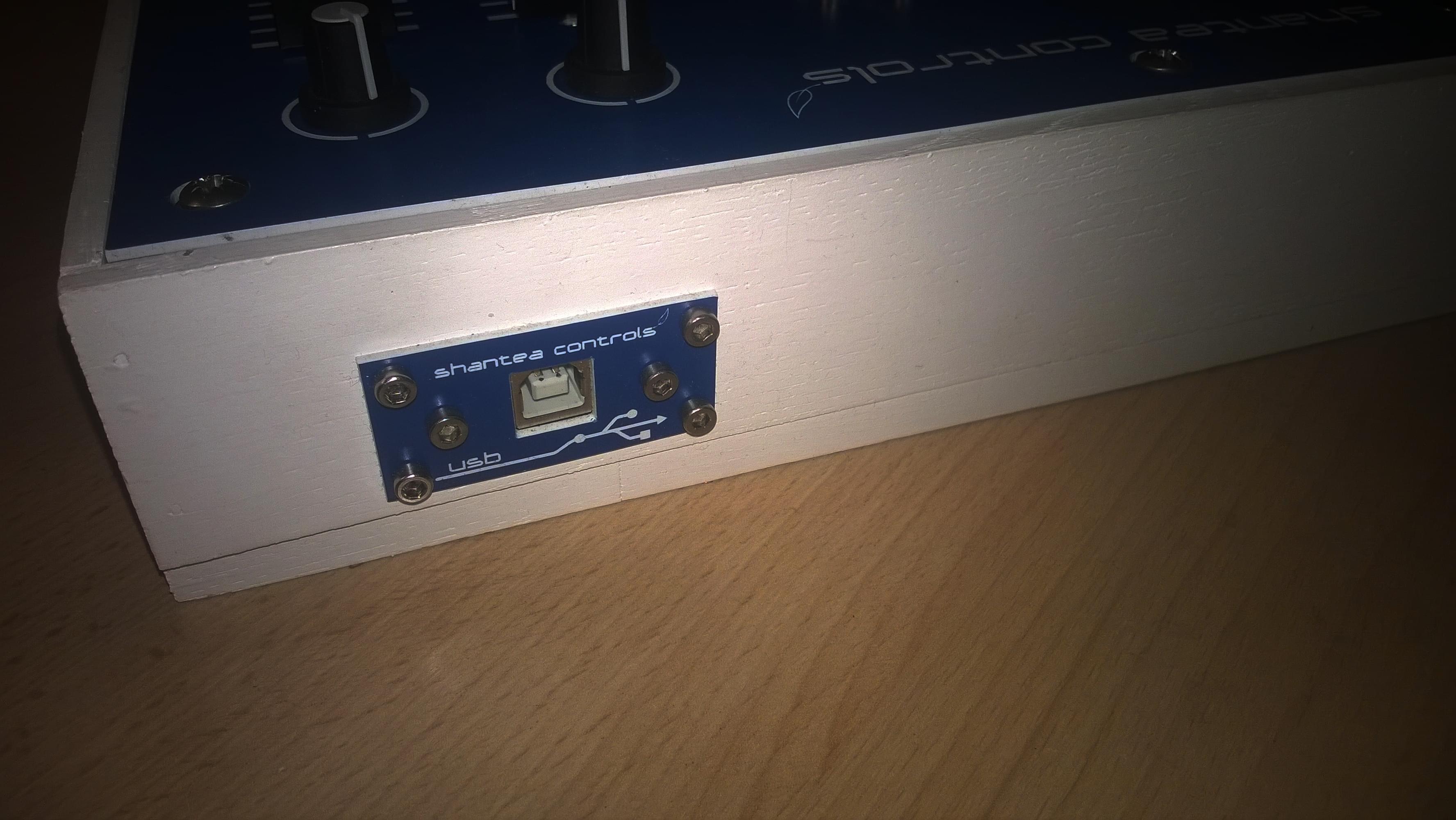
I also redesigned USB plate.
Case is white again, just like Tannin.
The disk
As I’ve already stated, only thing new in Ceylon is the disk. So, how does it work? The motor in mechanical hard disk generates phase-shifted sinusoidal waveforms when spinned. The faster you spin it, larger the amplitude and frequency of waveforms. By examing waveforms, you can determine disk direction, which is what I needed. There are couple of issues with this:
1) Signal amplitude is way too low to be sampled directly by a microcontroller, unless you spin the disk real fast, which is kind of missing the point of whole setup as you want fine grained control. My measurements showed that disk generates +-500mV when spinned at maximum speed (maximum being somewhat subjective term, I spinned it by hand).
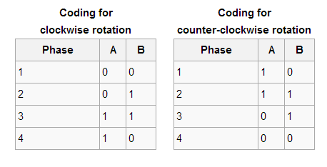
2) For encoders, you don’t actually need analog signals, but digital ones. By examining output data from two encoder pins, you can easily determine its direction. Those two outputs are called quadrature outputs, as they are 90 degrees out of phase.

Making the signals digital
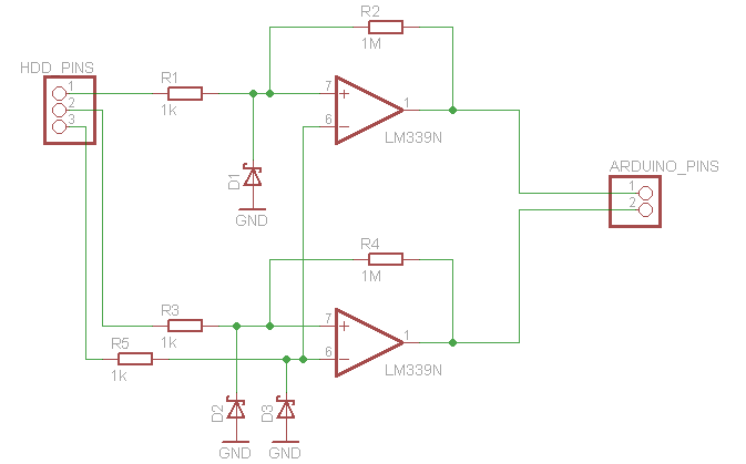
Basically, what this setup needed was ADC (analog-to-digital converter). For this use, I’ve chosen LM339, a very cheap, available and popular comparator. LM339 contains four comparators in a package, making it suitable for this setup, as I needed only two. Comparator takes two inputs, and simply determines which one is bigger. If voltage on non-inverting input (+) is larger than voltage on inverting input (-), output is digital 1, or Vcc, and if non-inverting input is smaller than inverting input, output is digital 0, or -Vcc (in this case GND). Very simple. But as usual, there are couple of caveats.
Issues
Connecting motor inputs directly to LM339 isn’t such a good idea, for two reasons:
1) What happens if two signals are very close to each other? Comparator would output bunch of ones and zeros very fast, which is actually junk, so you get unreliable results.
2) According to LM339 datasheet, you cannot apply more than -0.3V at either of its inputs. This is a problem, as disk actually outputs about -0.5V when spinned real fast.
Hysteresis
It took me really long to figure out what hysteresis actually is, but it’s actually really simple. Using hysteresis on comparator, you are creating two thresholds for generating two output states, that is, you are setting one threshold for output to be Vcc, and second one to be -Vcc, that is GND. This is achived by applying positive feedback from output back to input, using two resistors. Since signal from motor is really low, I’ve designed hysteresis for low values, just to keep signal from circling around switch point. Hysteresis is calculated using this formula:
Vth+ = -VN ∙ (R1 / R2) Vth- = -VP ∙ (R1 / R2)
Vth is threshold voltage, Vn is negative output (in this case 0V), and Vp is positive output (+5V in this case). I wanted to set positive threshold above 0V, and negative below -5mV, so resistor values are 1k for R1, and 1M for R2:
Vth+ = -0 * (1000/1000000)
Vth+ = 0V
Vth- = -5 * (1000/1000000)
Vth- = -5mV
So, when positive input voltage is above 0V, output is 1, and only when negative input drops below -5mV, output is 0. This way I created “dead zone”, or area where my signal can be of any value (between 0 and -5mV), without affecting the output of comparator.
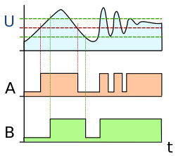
Graph is showing the input signal (U), usage of comparator on that signal without hysteresis (A), and output signal from comparator with applied hysteresis (B).

Picture above shows hysteresis setup. This is how you debounce your inputs using hysteresis, so that your output never becomes gibberish.
Voltage clipping
Now, there is one more concern. As I stated already, inputs on LM339 cannot be smaller than -0.3V. To accommodate this, I used BAT46 Schottky diode on inputs, having anode connected to ground. When the input is positive, diode doesn’t do anything as current cannot pass through. When the input is negative, diode still won’t do anything, as long as input voltage doesn’t become smaller than -0.3V. Those diodes have a voltage drop of about 0.3V (how convenient), so, when input voltage exceeds -0.3V, current will pass through diode, and voltage on comparator input will actually be voltage drop on that diode, and it will not exceed those -0.3V. Two problems solved, yay!
Software side of things
Now that I’ve taken care of hardware, it was time to actually read and process signals from motor. For this, I’ve used modified encoder library for Teensy/Arduino. Library is great as it has two really clever parts:
1) Since it’s written with Teensy/Arduino in mind, it automatically detects whether the pins on your microcontroller on which you’ve connected encoder have interrupt capability. If they do, library reads encoder using interrupts. Since HDD motor can be spinned real fast, I’ve connected both motor pins to interrupts (pins 2/3 on Arduino) in order not to miss any pulse. Pins 2 and 3 are two out of four unused pins on my OpenDeck board, so this was very convenient.
2) It has “predicting” algorithm, giving your encoder 4x more resolution. This is achieved by remembering previous state of pins, and comparing it to current state of pins with a lookup table. Lookup table contains valid encoder transitions:
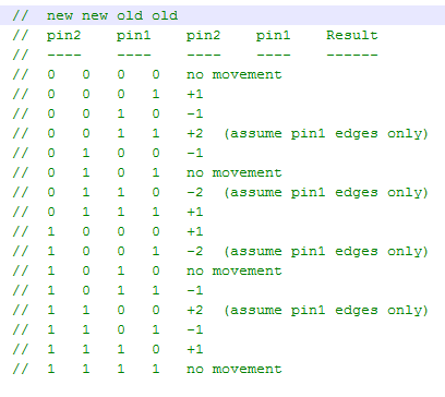
This works really, really well, but since HDD motor jumped a bit when changing direction, I’ve implemented additional debouncing:
void OpenDeck::readEncoders(int32\_t encoderPosition)
{
    if (\_board == SYS\_EX\_BOARD\_TYPE\_OPEN\_DECK\_1)
    {
        if (encoderPosition != oldPosition)
        {
            if (millis() - lastSpinTime > ENCODER\_DEBOUNCE\_TIME)
              initialDebounceCounter = 0;

            if (encoderPosition > oldPosition)
            {
                if (!direction)
                {
                    initialDebounceCounter = 0;
                    direction = true;
                }

                if (initialDebounceCounter >= ENC\_STABLE\_AFTER)
                  sendPotCCDataCallback(127, 127, 5);
                else
                  initialDebounceCounter++;
            }
            else if (encoderPosition < oldPosition)
            {
                if (direction)
                {
                    initialDebounceCounter = 0;
                    direction = false;
                }

                initialDebounceCounter++;

                if (initialDebounceCounter >= ENC\_STABLE\_AFTER)
                    sendPotCCDataCallback(127, 1, 5);
                else
                    initialDebounceCounter++;
            }

            oldPosition = encoderPosition;
            lastSpinTime = millis();
        }
    }
}
If there is a movement detected, code first checks for whether the disk hasn’t been moved for more than ENCODER_DEBOUNCE_TIME (70mS). If it hasn’t, it resets the debounce counter. This is to avoid extra pulses when disk is slowing down. After that, initialDebounceCounter variable is incremented until it reaches 1. This is to prevent disk jumping when changing direction.
So there you have it, a pretty good resolution from HDD motor for use in MIDI controller! In all honesty, its resolution is far from optical encoders, but as this is more of a proof-of-concept, I’m really satisfied with results.
LEDs on anti-vandal switches
This was another issue that I had while building Ceylon. Anti vandal switches (the ones around the disk) I had around have blue LED on them. Their pins are separated from button pins. Those button pins can be connected in NC and NO configuration, so there’s 5 pins in total. Since I’m using shared column button/LED matrix in my OpenDeck platform, I’ve connected - pin of LED and one of button pins together, going into same column, and then + pin of LED into LED row, and second button pin to button row. Nothing out of ordinary, right? Well, something weird was happening with this setup. Whenever I pressed the button, LED on it lighted up. This is not the behavior that I expected nor wanted, so for a while I had no idea what was happening. Only few days later, I’ve discovered that it doesn’t really matter where you connect + and - of the integrated LED on button, since there are 2 LEDs inside, one of which has anode on + pin, and second one on - pin.
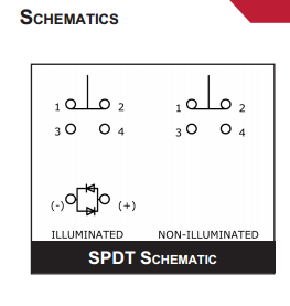
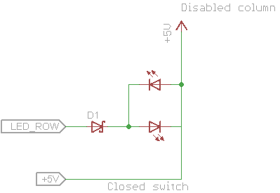
Okay, but why does the LED turn on when button is pressed? For this, answer is in matrix setup. LED/button matrix works by switching columns very rapidly. Only one column is active at the time, and during that time, it is connected to GND, while others are connected to Vcc. When button is pressed, connection from microcontroller input on which button is connected goes to GND, and button press is registered, but only during the time the column is active. When column isn’t active anymore, it’s connected to Vcc. Since those switches have two LEDs inside, one of which has anode on - pin, when button is pressed, and column isn’t active, that anode is actually connected to Vcc, and LED row on microcontroller starts acting like current sink, so LED is lighted up.
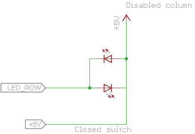
In order to solve this, I’ve placed Schottky diode (to minimize voltage drop) between LED anodes and microcontroller LED row pin, so that the current is blocked for second LED inside switches.
Demo
So, to conclude this post, here’s a short video of Ceylon in action, together with Tannin.
And also some higher quality pictures of Ceylon.
Thanks for reading!


