I’ve been real quiet about this project for more than a month, but not because I haven’t done anything. Quite the opposite, I literally got consumed by work invested in this project. I realized there’s much more stuff to do than I thought. As I mentioned last time, the project consists of three distinct parts:
- PCB
- MCU software
- GUI application
Apart from some mockups, there’s nothing else I’ve done with GUI for the time being, so I’ll just talk about first two points.
PCB
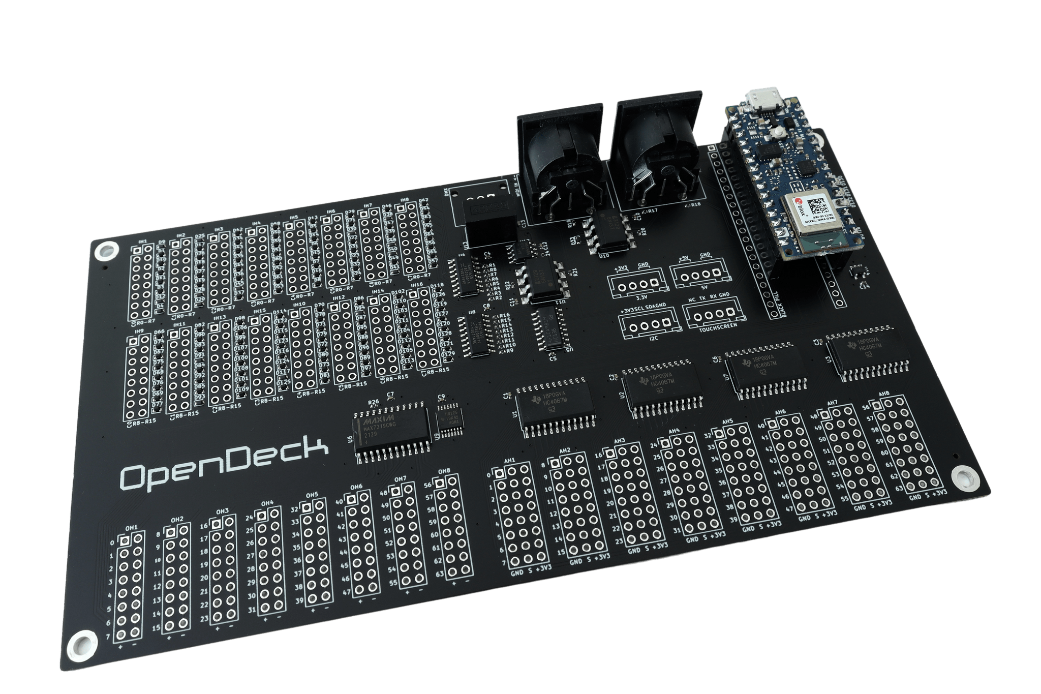
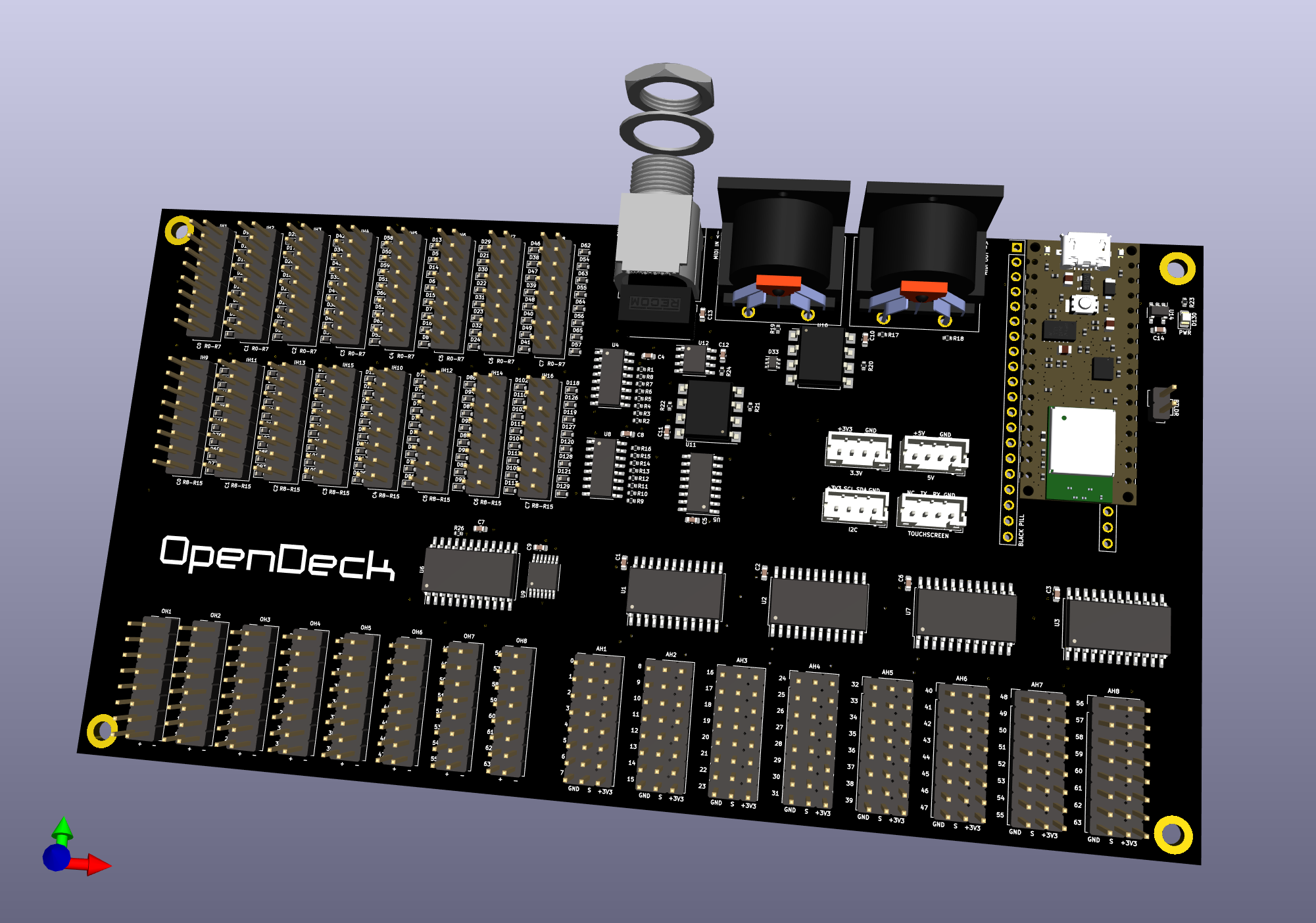
I’ll repeat what I said about PCB last time: it has 32 digital inputs, 32 digital outputs and 16 analogue inputs. As far as digital stuff is concerned, it’s a simple 8x4 matrix with shared columns for both buttons and LEDs. The column switching is done via 74HC238 decoder. Its outputs are connected to ULN2803 transistor array, since Arduino alone can’t handle that much current sink when all 4 LEDs are turned on in a column. Button and LED rows are connected directly to Arduino (with 220Ohm resistor for each LED row). 16 analogue inputs are handled with two 4051 multiplexeres. All in all, fairly simple circuit. Bonus features I’ve came up with are 4 additional configurable I/O pins, which you can configure in GUI app (but not right now, since GUI isn’t finished yet, and there’s not even support for those pins in MCU code). So in essence, you could use those four pins to add two additional rows in button matrix and two rows in LED matrix, resulting in total of 48 buttons/LEDs. Or you can use all four to add 32 additional buttons. Or LEDs. There is some flexibility involved in any case. Here’s how the PCB looks:
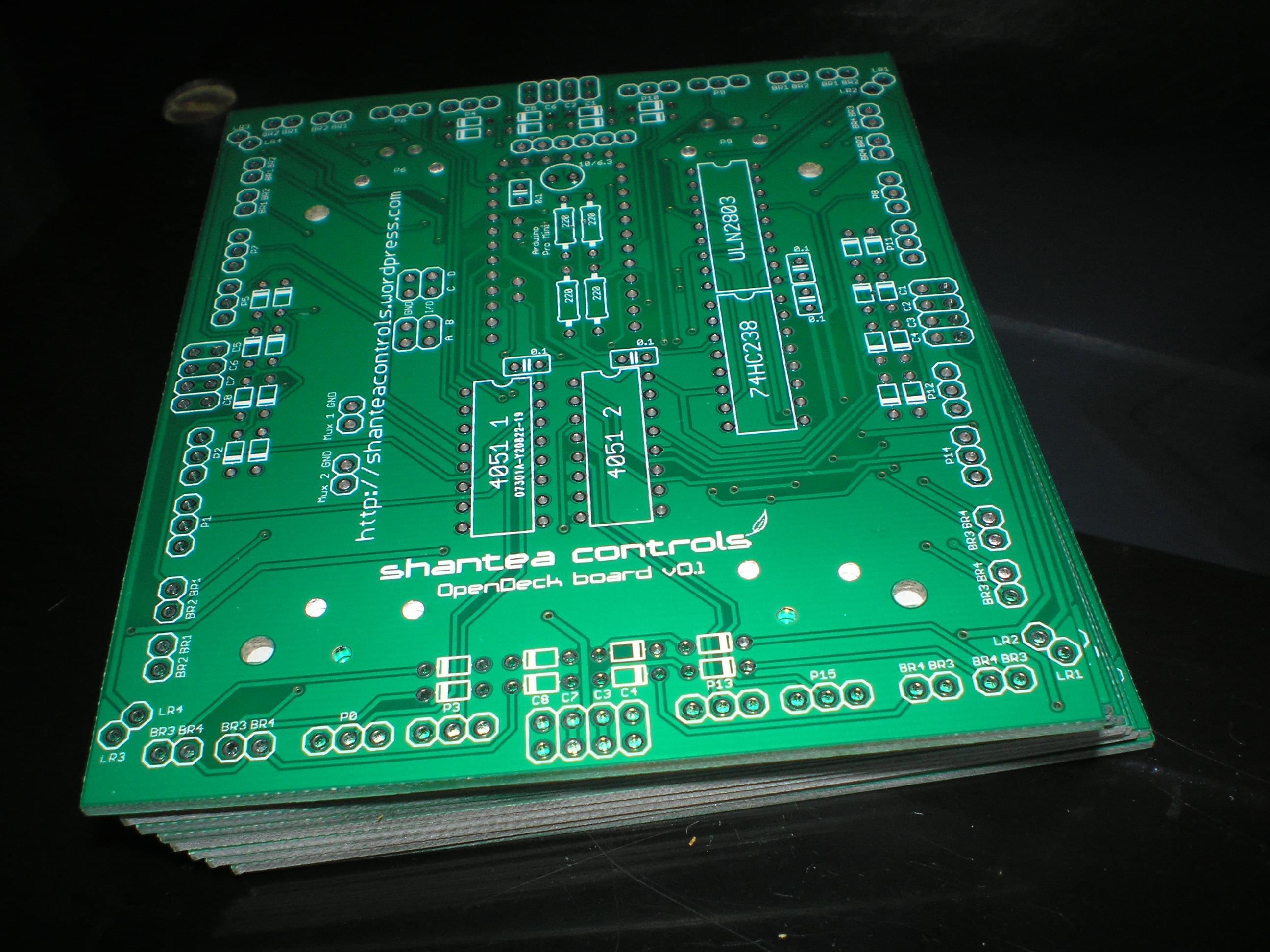
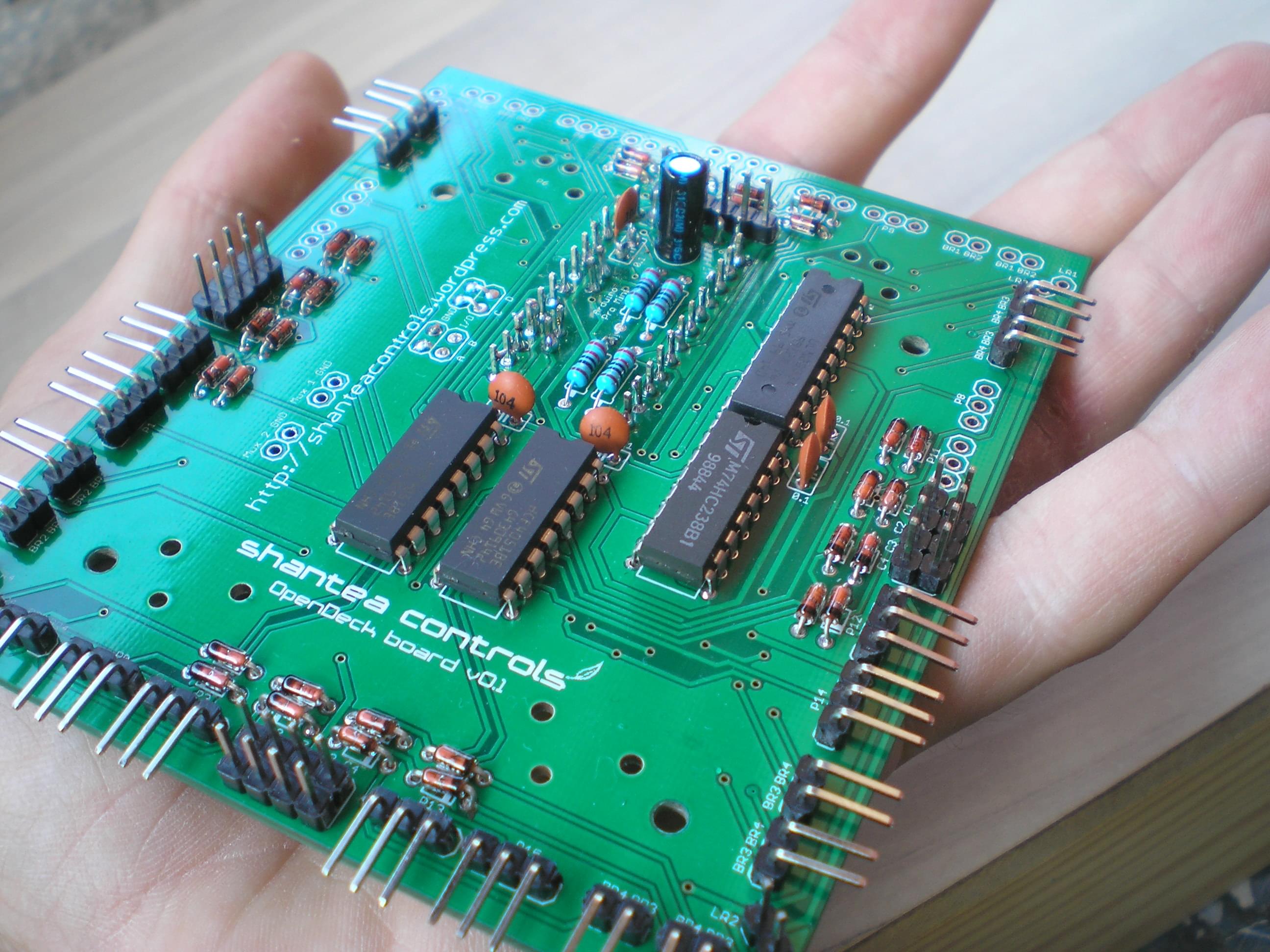
Since I’m already using it in a project I’ll talk about soon, I can tell you that everything works perfectly. No wrong connections or any electrical problem. I did manage to reverse poteniometer labeling though: pots 0-7 are actually 8-15, and vice versa. Annoying? Kinda. Deal breaker? Most certainly not. I’ve also added ground shortcuts to multiplexer inputs, so if you’re not using one of multiplexers (or both), you can quickly shortcut them to GND to avoid floating pins.
That’s how the board looks like with most of the stuff soldered. There is one (hardly) visible issue: Right above of the ‘A’, ‘B’, ‘C’ and ‘D’ pins (which are those configurable pins I’ve talked about) are GND pins. I intended it to be quick way to shorcut those four pins to GND if they’re left unused, since I don’t like having any pins floating. Now, there is nothing inherently wrong with that idea, except that you can’t simply ground some pins on ATmega chips. I’ve learned it the hard way. After I’ve done all the soldering, naturally I’ve connected all four of those pins to GND since the project I’m using this board for at the moment doesn’t require them. I’ve connected the board to USB via CP2102 serial-to-usb converter, but the LED connected to pin 13 on Arduino didn’t blink at all. After you connect the board to USB, that LED blinks for 6 seconds, after which your code starts running. In this case, only the power LED got turned on, so there was apparently something fishy going on. First I simply tried to upload code to the board using serial converter, but that didn’t work. I think the message in avrdude said something along the lines of “board is not responding”, or similiar. Weird. After that, I assumed that maybe I accidentally removed the bootloader while I was playing with the Arduino couple of days earlier. I connected my USBASP programmer to the board (or more precisely, soldered the cables to pins sticking out since I had no other way of doing it) and decided to simply burn the bootloader onto the board, but that also didn’t work. I got similiar message like when I tried to upload new code via serial converter. Damn. After that, I started to wonder that maybe 10nF electrolytic cap and 0.1uF cap are too much capacitance, causing the board not to work properly, because I had the same scenario with my USB MIDI PCB (you can read about it couple of posts below). So I simply cut the 0.1uF cap at first to see what happens (that’s why the cap right next to the electrolytic cap may seem a bit weird, because later I’ve re-soldered it). Nothing. Then I almost cut the electrolytic cap as well, when it hit me. When you upload new code to your board via external programmer, you connect MOSI, MISO, SCK, reset, VCC and GND pins from programmer to ATmega. MOSI, SCK and MISO are pins 11, 12 and 13 on Arduino board. The unused ‘A’ and ‘B’ pins are actually pins 12 and 13 on Arduino. See the problem here? How the hell am I supposed to upload new code to board via pins which are connected to GND? Then I simply removed the solder shortcuted to GND pins, and magically, board worked. Another lesson learned. Apart from that, there were no other issues.
MCU code
There’s been many changes and optimizations in code since the last time I posted. I removed HardwareReadSpecific library since hardware control is being handled via callbacks now, so all the configuration is being done within main program now. There is added benefit of being able to compile the whole OpenDeck library as a single file and simply including it as precompiled binary in other projects, but since it’s still under heavy development, I wouldn’t have any use from it. I’ve also made a “database” of parameters in EEPROM, like MIDI channels, blink time, button notes, CC numbers etc. There’s also array of default parameters in code, so that there’s an option of performing “factory reset” of MIDI controller. I’ve saved those default parameters in PROGMEM part of ATmega memory, since I would’ve wasted limited amount of available SRAM otherwise. 1kB of EEPROM may sound like tiny amount of space, but in reality it really isn’t. You are free to check the code on my GitHub page. I still have to design my own SysEx protocol to program the controller. I hope I’ll manage to finish that in the next few days, after which I can move on to GUI app.
That would be all for now.